what type of cover to install at ground level for a curb stop
Flashing at Bottom of Exterior Walls
Scope
Install flashing at bottom of all outside walls and properly integrate the flashing with other wall water management details to direct water downwardly and out of the wall.
-
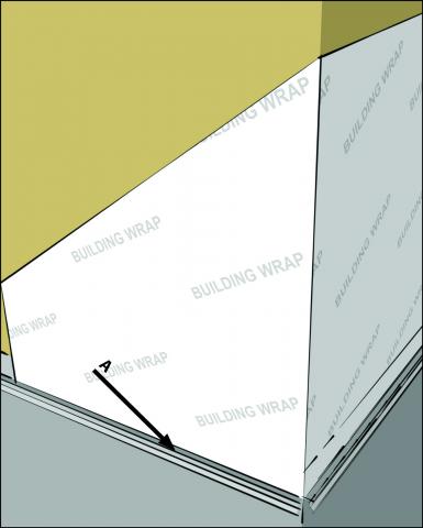
Install flashing under the lesser edge of the house wrap or other atmospheric condition-resistant bulwark shingle fashion to direct h2o out of the wall.
-
Stucco cladding – install self-adhesive flashing behind the weep screed, a perforated metallic strip at the base of the exterior walls, at the peak above grade specified by the local edifice code. Install the water-resistant barrier to overlap the superlative edge of the weep screed. Install the lathe and stucco to the kickoff curve in the weep screed.
-
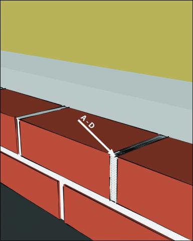
Brick veneer – install metal or flexible through-the-wall flashing that starts behind the bottom edge of the weather-resistant barrier and extends down and out beyond the support ledge then hangs down. Ensure that weep holes are included in the bottom course of brick to permit water to drip out and down the flashing. Install in brick walls at the base of walls, above all window and door lintels, and above shelf angles.
Encounter the Compliance Tab for related codes and standards requirements, and criteria to meet national programs such as DOE's Goose egg Energy Fix Dwelling house program, Free energy STAR Certified Homes, and Indoor airPLUS.
Description
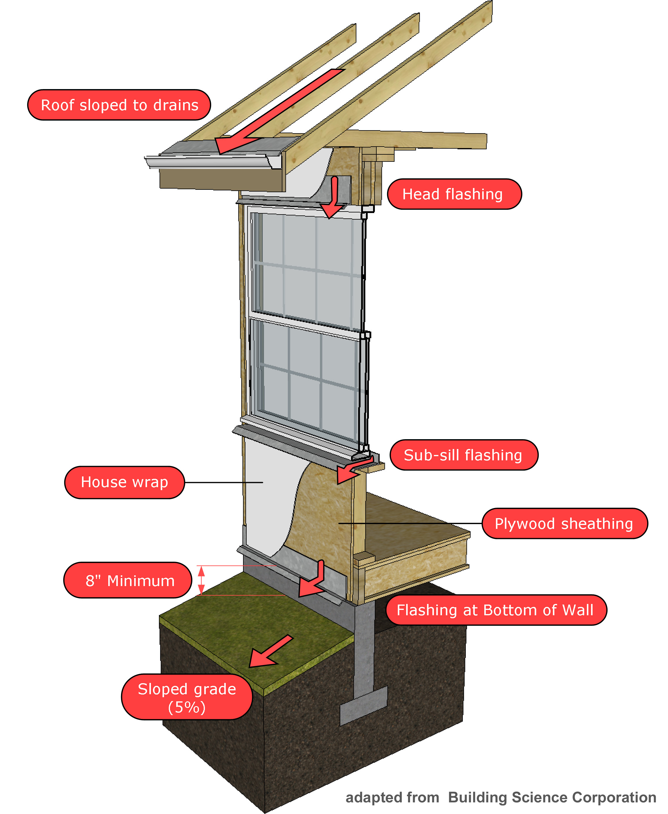
Flashing at the lesser of exterior walls needs to be integrated into a continuous drainage plane on the outside wall. The goal is to create a wall organization that can manage the water that will inevitably become behind any cladding organization.
Principles of a H2o Managed Wall System
Water leaking through exterior cladding assemblies is a common cause of construction defects and call-backs.
Typically, these wall leaks are caused by missing flashings or poorly executed flashing details at the post-obit:
- roof-to-wall intersections
- penetrations
- windows and doors
- transitions between different claddings when more than one cladding is used at the bottoms of outside walls where cladding systems interface with the foundation.
The key to eliminating costly leaks is more than than just applying a piece of flashing. Y'all need to create a functional wall assembly that:
- Deflects h2o abroad from sheathing, framing and flooring-to-foundation intersections.
- Drains water as fast and freely as possible to prevent water from being trapped and absorbed by edifice components.
- Dries. Select building materials that allow the wall to dry out when it gets wet, and avoid materials that have the ability to trap moisture (BSC 2007).
Continuous Drainage Plane
Drainable wall assemblies integrate a weather-resistive barrier and flashing to properly drain water away from building components. The specific materials and installation methods depend on the cladding used on the edifice. House wrap and flashing must be properly integrated to create a continuous drainage plane. Notation in Figure 2 that the flashing at the bottom of the wall is merely 1 of a number of wall details that work in concert with each other to ensure water drains downwardly and away from the building (Straube 2007).
Installation Sequence
A continuous drainage plane is typically created using a weather-resistive barrier (WRB), such as edifice paper or housewrap. To work effectively, the conditions-resistive barrier must be properly "shingled." Shingling is a term that describes the installation sequence that will allow water to drain away from the wall.
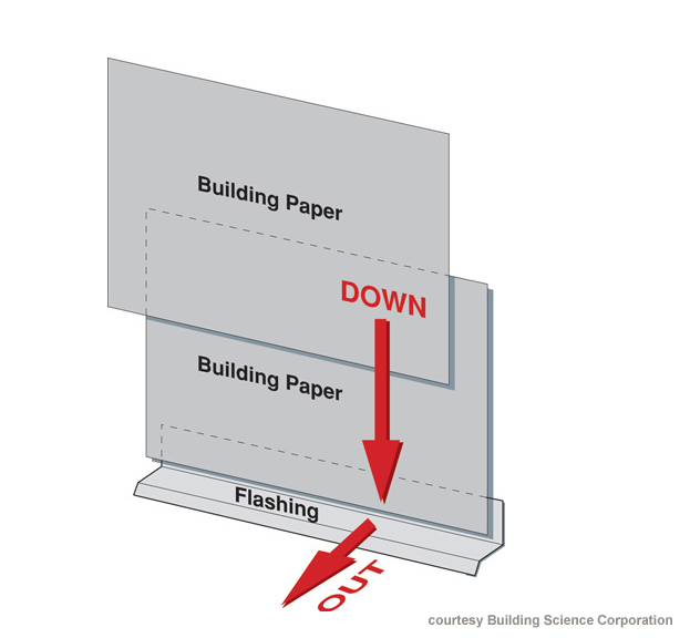
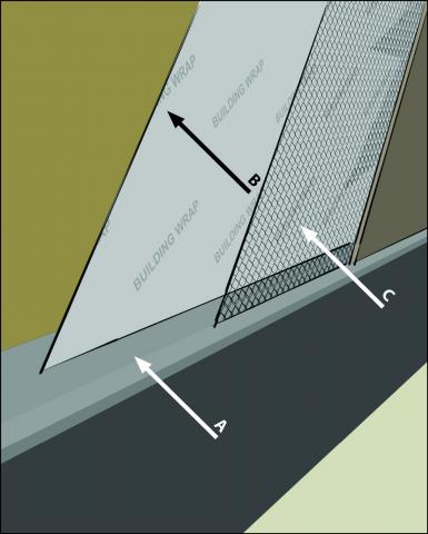
Figure 3 shows how the layers of the weather-resistive bulwark must overlap to divert water out and away from the construction. In the sequence of construction, the flashing would need to be installed offset. The bottom layer of building paper would be installed next, overlapping the vertical leg of the flashing. The top layer of edifice paper would be installed last (BSC 2007).
Rain screen wall systems as well provide an air space betwixt the wrap and the cladding. This air space helps reduce water issues in several ways.
- The larger infinite can create faster, unobstructed drainage.
- The space creates a capillary pause to preclude water from wicking into building materials.
- The space allows for additional air motion to facilitate drying.
- The space can provide force per unit area moderation and help reduce pressure differentials that can help draw water into openings in the cladding.
- Helps prevent h2o vapor from the cladding from being driven into the wall assembly.
The air infinite varies depending on the cladding cloth. Wall venting behind brick and stone veneers is especially of import. Nether the right weather, energy from the sun can button vapor through wet brick with the strength of a steam boiler. A ventilation gap behind brick helps to dissipate this vapor before it is injected into the framed wall cavity. The gap should be 1 or more inches behind brick or stone veneer, 3/four inch behind stucco, and ane/16 inch backside lap siding (Wrinkled house wrap will provide this 1/16-inch gap.)
How to Construct a Drainable Wall Assembly with Wood or Cobweb-Cement Sided Walls
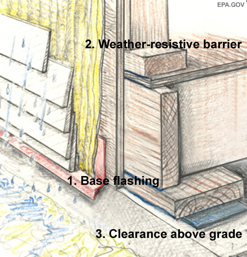
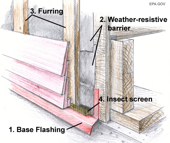
- Base flashing. First past installing a metallic or vinyl base flashing first. This piece should exist applied directly to the wall sheathing using roofing nails. When more than one length is needed to span across the lesser of a wall, overlap pieces at to the lowest degree 8 inches. The flashing must include a drip-edge to direct any water that runs downwards the drainage plane abroad from the bottom of the wall.
- Weather-resistive barrier. Next, a weather-resistive bulwark, such every bit building paper or house wrap, is applied to the wall, overlapping the base flashing. The example pictured in Effigy 4 is a "bleed wrap," which has a texture to it to facilitate drainage after the siding is applied over it. You don't need a drain wrap to create a drainable wall assembly, only the texture drains water faster than conventional smoothen house wraps. There are several types of drain wrap: i blazon has a wrinkled surface; ane type has plastic bumps that create a infinite between the wrap and the cladding (Smegal and Lstiburek 2012).
- 8-inch minimum between siding and form. To prevent splash back from the roofline soaking the base of operations of the wall, the bottom edge of the base flashing should exist at least 8 inches above grade. This is a design detail that must be worked out earlier the foundation is poured. The grade must be sloped on all sides of the building so the water continues to drain abroad from the building. A 5% slope is recommended. This is a 5-inch drop per 100 feet, or most 5/eight-inch per foot (Straube 2007).
How to Construct a Drainable Wall Assembly with Stucco Clad Walls
Stucco is porous and volition always crack. This is true even when installed perfectly. It is brittle, and groovy is in its nature. However, while these shortfalls volition lead to h2o getting through the surface, the water can be managed. The key is to create a proficient drainage plane behind the stucco that drains to a weep system, allowing the water to menstruum out and away from the edifice.
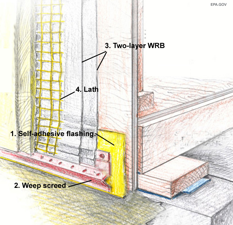
- Self-adhesive flashing. When the weep screed attaches to plywood, OSB, or another wood-based framing material, a cocky-adhesive flashing membrane is needed first to protect the forest from water draining through the perforated screed (EPA 2015).
- Weep screed. Next, a weep screed is installed. The bottom edge of this piece of flashing should extend onto the foundation. The size of the screed will depend on the stucco thickness, with traditional iii-coat stucco requiring a deeper profile than the screed needed for a i glaze organisation. On an outside insulation and end (EIF) arrangement, this flashing piece is called a weep aqueduct, and it holds the bottom edge of the foam. It is perforated and works in principle merely like a weep screed (EPA 2015).
- Two-layer weather resistive barrier. Nigh edifice codes require two-layers of building newspaper (or some other blazon of weather-resistive barrier) beneath the stucco. The first layer (installed against the sheathing) serves as the drainage plane and protects the wall sheathing from h2o. The second layer works as a bail breaker. Wet stucco tends to adhere to building paper and house wrap. H2o captivated by the stucco will wick right through this bond breaking layer, but volition drain down the wall between the two layers. Both layers should overlap the peak edge of the weep screed (Lstiburek 2003).
- Lath. On wood framing, wire board must be installed with the long dimension running perpendicular to the wall studs. All-time practice calls for securing lath with furring nails, which place the lath in the center of the scratch coat (Note: Using paper-backed lath over a single-layer of house wrap or building newspaper will work as well equally a 2-layer weather resistive barrier and will save time) (DeKorne 2006).
How to Construct a Drainable Wall Associates with a Rain Screen Air Gap for Wood or Cobweb-Cement Siding
Best practise with any wood or cobweb-cement siding calls for building a pelting screen assembly. This technique uses all the same water management details of a drainable wall associates, but adds an air infinite behind the siding. This space creates a capillary break, which prevents water that wicks through the siding from being absorbed into the water-resistive barrier. The air space also allows air to period freely behind the siding, which increases the wall's ability to dry out.
- Base flashing. The wall arrangement begins with flashing at the lesser of the wall, which collects h2o that drains down the wall and kicks it out at the base. Metal or PVC flashing can be used. It should have a drip border that hangs beneath the sill plate, with the bottom edge at least 8 inches above grade (EPA 2015).
- Conditions-resistive bulwark. After the flashing, a weather-resistive barrier (WRB), such as building paper or a firm wrap is installed to create a drainage plane. The first class of the WRB needs to overlap the vertical leg of the base flashing. Subsequent courses of the WRB must overlap the class below (EPA 2015).
- Furring. The air space is created by installing furring strips (vertical pieces of forest or plastic) spaced every 16-24 inches over the weather-resistive barrier. These need to be at least 3/8 inches thick. They can be ripped out of plywood or purchased precut from a lumberyard, and nailed every 12-xvi inches with 5d galvanized nails (Hanley-Forest 2007).
- Insect screen. To cake the entry of insects, install nylon screening. Tuck the screening behind the furring strips, wrap information technology effectually the ends of the strips, and pin it in place with the siding starter strip. Nylon is recommended, merely other types of screening can be used, as long as it is an open mesh that will not block the gratis menstruation of air. Metal will rust and is not recommended (EPA 2015).
How to Construct a Drainable Wall Assembly with a Rain Screen Air Gap for Brick Veneer Siding
Properly detailed brick veneer functions like a rain screen. The fundamental is making sure there is an unobstructed path for water to flow out at the bottom of the wall. This path starts with the airspace behind the brick. Water freely flows down through this space, gets collected past through-wall flashing at the bottom of the wall, and drains out through cry holes.
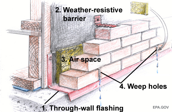
- Through-wall flashing. The first step to detailing the base of a brick-veneer wall is to install a through-wall flashing, which extends downwards the sheathing and out across the support ledge (often a concrete extension of the foundation, simply may also be formed with angle-fe).
Through-wall flashing can be made with metal, but is usually formed with a flexible safety-based membrane, such as the one shown in Effigy viii (Hanley-Woods 2007).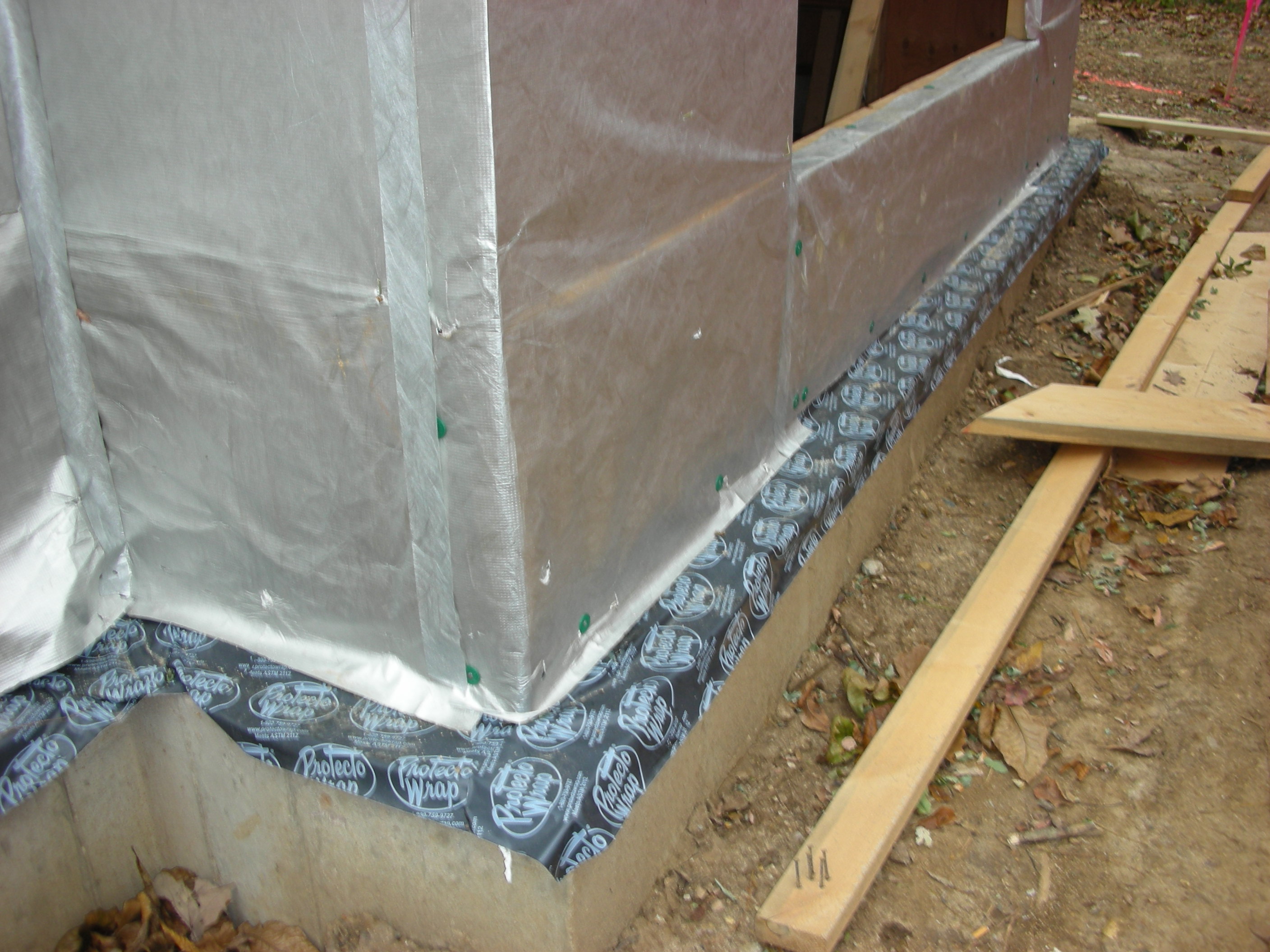
Figure 8. A flexible safe through-wall flashing overlaps the bottom of the capsule and works with the conditions-resistant barrier to guide any water that gets past the brick down and out of the wall. - Weather condition-resistive bulwark. Next, a weather-resistive bulwark, such every bit building paper, must exist practical over the framed wall assembly. The courses of the weather-resistive barrier must exist applied "shingle way," with the lowest class practical first, overlapping the vertical leg of the through-wall flashing. The upper courses are installed afterwards, overlapping each lower course (EPA 2011).
- Air space. The brick must be installed with a i-inch air space behind information technology to allow water that seeps into the brick to freely bleed. The illustration above shows a mortar mesh installed in the air space at the base of wall. This helps to terminate mortar droppings from clogging the weep holes (EPA 2011).
- Weep holes. Water that collects on the through-wall flashing must be able to drain out through cry holes, which are formed by an "open" head articulation (as shown in the analogy higher up), or with rope inserted into the mortar joint (equally shown in the photo beneath). In this illustration the open caput joints have been filled with an open-weave mesh. This is a skillful thought for keeping mud wasps from building their nests in the cry holes, and to forestall other obstructions from blocking the complimentary flow of h2o (EPA 2012).

Figure 9. Rope is inserted in the head joist between the bricks in the everyman grade of bricks to allow water to weep out of the base of the wall assembly.
Ensuring Success
Builders and subcontractors should follow a protocol for water management details in exterior walls such as the Energy STAR Qualified Homes Water Direction Organisation Builder Checklist.
The project supervisor should inspect for flashing at the base of walls and at transitions between sidings before the siding is installed. This inspection should confirm that the weather-resistive barrier (WRB) overlaps the base of operations flashings (EPA 2011).
Success with stucco
For wood-framed structures, hang the drywall before the lath and scratch coat are applied. Otherwise, the weight of the drywall volition stress the forest framing, causing early on settlement cracks, which can be acute if the drywall is hung before the scratch coat has had a chance to cure (DeKorne 2006).
Climate
The chief climate gene is exposure to rainfall. Buildings in regions with more rainfall are subject to increased incidence of water damage.
Drainable wall assemblies are recommended in all exposure regions. Rain-screen wall systems are considered best-practice upgrades in all exposure regions to ensure the long-term durability of building assemblies, but are especially recommended in High and Extreme exposure regions, as shown on the map below (BSC 2004).
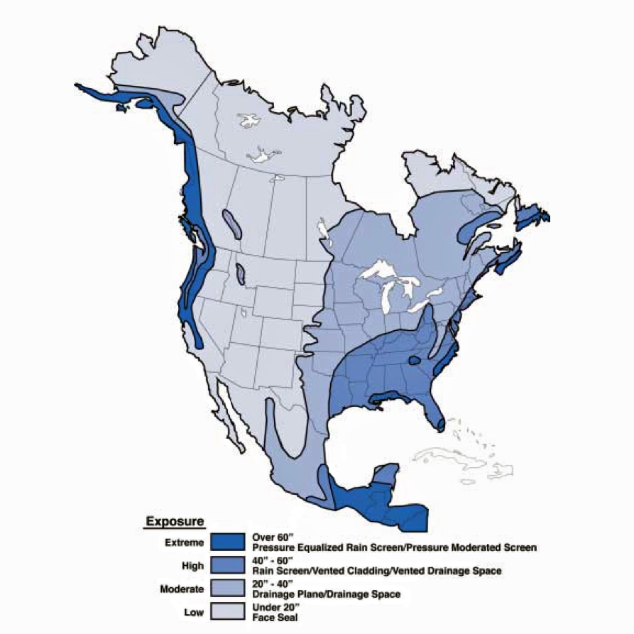
Figure ane. Average Annual Precipitation Map.
The Compliance tab contains both plan and code data. Code linguistic communication is excerpted and summarized below. For exact code language, refer to the applicable code, which may require buy from the publisher. While we continually update our database, links may accept changed since posting. Delight contact our webmaster if y'all notice broken links.
ENERGY STAR Certified Homes, Version 3/three.1 (Rev. 09)
Water Management System Builder Requirements
2. Water-Managed Wall Associates.
2.1 Flashing at bottom of exterior walls with weep holes included for masonry veneer and weep screed for stucco cladding systems, or equivalent drainage organization.9
Footnote 9) These Items not required for existing structural masonry walls (e.g., in a dwelling undergoing a gut rehabilitation). Note this exemption does non extend to existing wall assemblies with masonry veneers.
Delight run across the ENERGY STAR Certified Homes Implementation Timeline for the program version and revision currently applicative in in your land.
DOE Null Free energy Ready Home (Revision 07)
Showroom 1 Mandatory Requirements.
Exhibit 1, Item 1) Certified nether the Free energy STAR Qualified Homes Plan or the Energy STAR Multifamily New Construction Program.
2009 International Residential Code (IRC)
Section R703.half-dozen.2.ane Cry screeds. A minimum 0.019-inch (No. 26 galvanized canvass gage), corrosion-resistant weep screed or plastic weep screed, with a minimum vertical attachment flange of 31/2 inches must be provided at or beneath the foundation plate line on exterior stud walls per ASTM C 926. It must exist placed a minimum of 4 inches above the globe or 2 inches higher up paved areas and must allow trapped water to bleed to the exterior. The weather-resistant bulwark must lap the attachment flange, and the exterior lath must cover and end on the weep screed zipper flange. Section R703.vii.5 Flashing. Flashing must be located beneath the first grade of masonry higher up finished footing level above the foundation wall or slab and at other points of back up, including structural floors, shelf angles and lintels when masonry veneers are designed per Section R703.7. Department R703.7.6 Weepholes. Weepholes must exist provided in the outside wythe of masonry walls at maximum spacing of 33 inches on eye and must be located directly above the flashing.
2012 IRC
Section R703.vi.2.1 Weep screeds. A minimum 0.019-inch (No. 26 galvanized sail gage), corrosion-resistant cry screed or plastic cry screed, with a minimum vertical attachment flange of 31/2 inches must be provided at or beneath the foundation plate line on outside stud walls per ASTM C 926. It must be placed a minimum of 4 inches above the earth or 2 inches above paved areas and must let trapped water to bleed to the exterior. The conditions-resistant barrier must lap the attachment flange, and the exterior lath must embrace and cease on the weep screed attachment flange. Department R703.7.v Flashing. Flashing must be located beneath the first course of masonry above finished ground level to a higher place the foundation wall or slab and at other points of support, including structural floors, shelf angles and lintels when masonry veneers are designed per Section R703.7. Section R703.7.6 Weepholes. Weepholes must exist provided in the outside wythe of masonry walls at maximum spacing of 33 inches on center and must be located directly above the flashing.
2015 and 2018 IRC
Department R703.7.two.1 Weep screeds. A minimum 0.019-inch (No. 26 galvanized sheet gage), corrosion-resistant weep screed or plastic weep screed, with a minimum vertical zipper flange of 3.5 inches must be provided at or beneath the foundation plate line on exterior stud walls per ASTM C 926. It must be placed a minimum of 4 inches above the earth or 2 inches above paved areas and must allow trapped h2o to drain to the exterior. The conditions-resistant barrier must lap the attachment flange, and the exterior lath must encompass and end on the cry screed attachment flange.
Section R703.eight.five Flashing. Flashing must be located below the first grade of masonry above the finished ground level above the foundation wall or slab and at other points of support, including structural floors, shelf angles, and lintels when masonry veneers are designed per Department R703.eight.
Section R703.8.6 Weepholes. Weepholes must be provided in the outside wythe of masonry walls at maximum spacing of 33 inches on center, must be not less than iii/xvi inch (5mm) in diameter, and must be located directly above the flashing.
Retrofit: 2009, 2012, 2015, 2018, and 2021 IRC
Section R102.vii.1 Additions, alterations, or repairs. Additions, alterations, renovations, or repairs shall conform to the provisions of this code, without requiring the unaltered portions of the existing building to comply with the requirements of this code, unless otherwise stated. (See code for additional requirements and exceptions.)
Appendix J regulates the repair, renovation, alteration, and reconstruction of existing buildings and is intended to encourage their continued safe use.
Existing Homes
Scope
Retrofit existing exterior walls past calculation base of operations flashing to improve drainage, which mitigates water leaks and extends the life of the cladding.
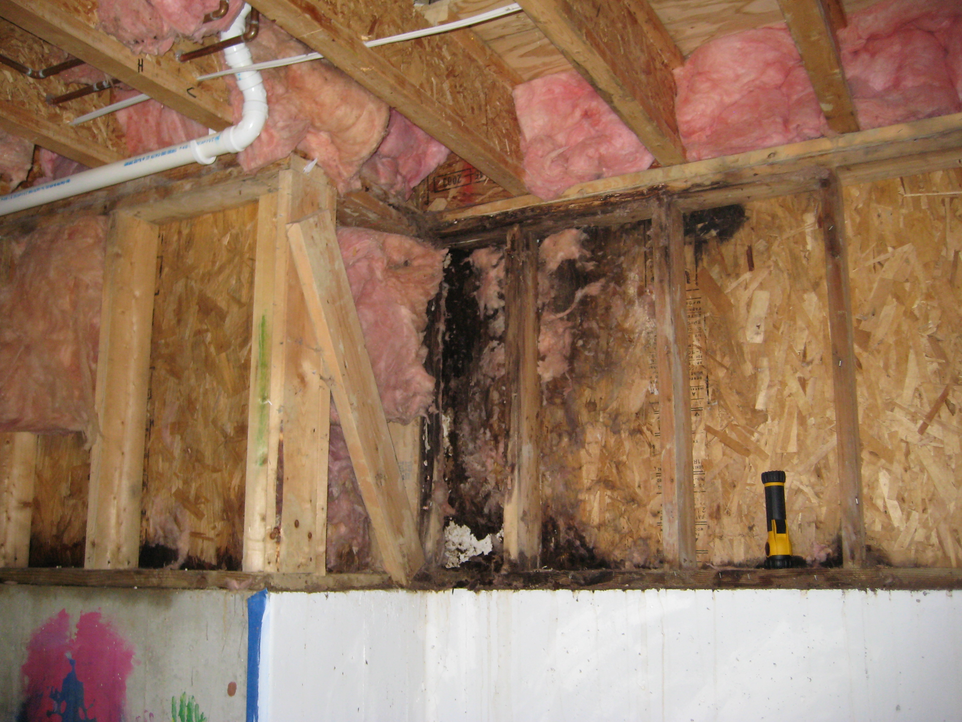
- Remove cladding at the base of the wall and examine exposed edifice wrap, felt paper, or water control membrane, and capsule below it.
- Repair torn or damaged building wrap as needed.
- If rotten sheathing is found, remove additional cladding equally needed to diagnose and ready water damage, removing and replacing all rotten sheathing, installing new edifice wrap and flashing, and reinstalling cladding every bit needed
- Install base flashing as described in the Scope and Description tabs.
- If in that location is no separate h2o control membrane (fluid applied membrane, building paper, or felt) on the sheathing behind the cladding, tape or seal the summit edge of the new flashing directly to the face of the existing sheathing with self-adhered membrane, sheathing tape, or sealant.
For more than information on conditions that may be encountered when working with walls in existing homes, run across the assessment guide on walls, windows, and doors.
See the U.S. Section of Energy's Standard Work Specifications for more on sealing walls to go along out wet, air, and pests. Follow safe work practices as described in the Standard Work Specifications.
Clarification
Existing exterior walls may be retrofitted to add flashing at their base to improve h2o direction, reduce staining, and extend the life of the cladding. Equally with new construction, the goal is to direct water that passes backside the cladding and reaches the house's h2o control layer downward and out, away from the building. (Come across Figure three in the Description tab for an illustration of the conceptual arroyo.)
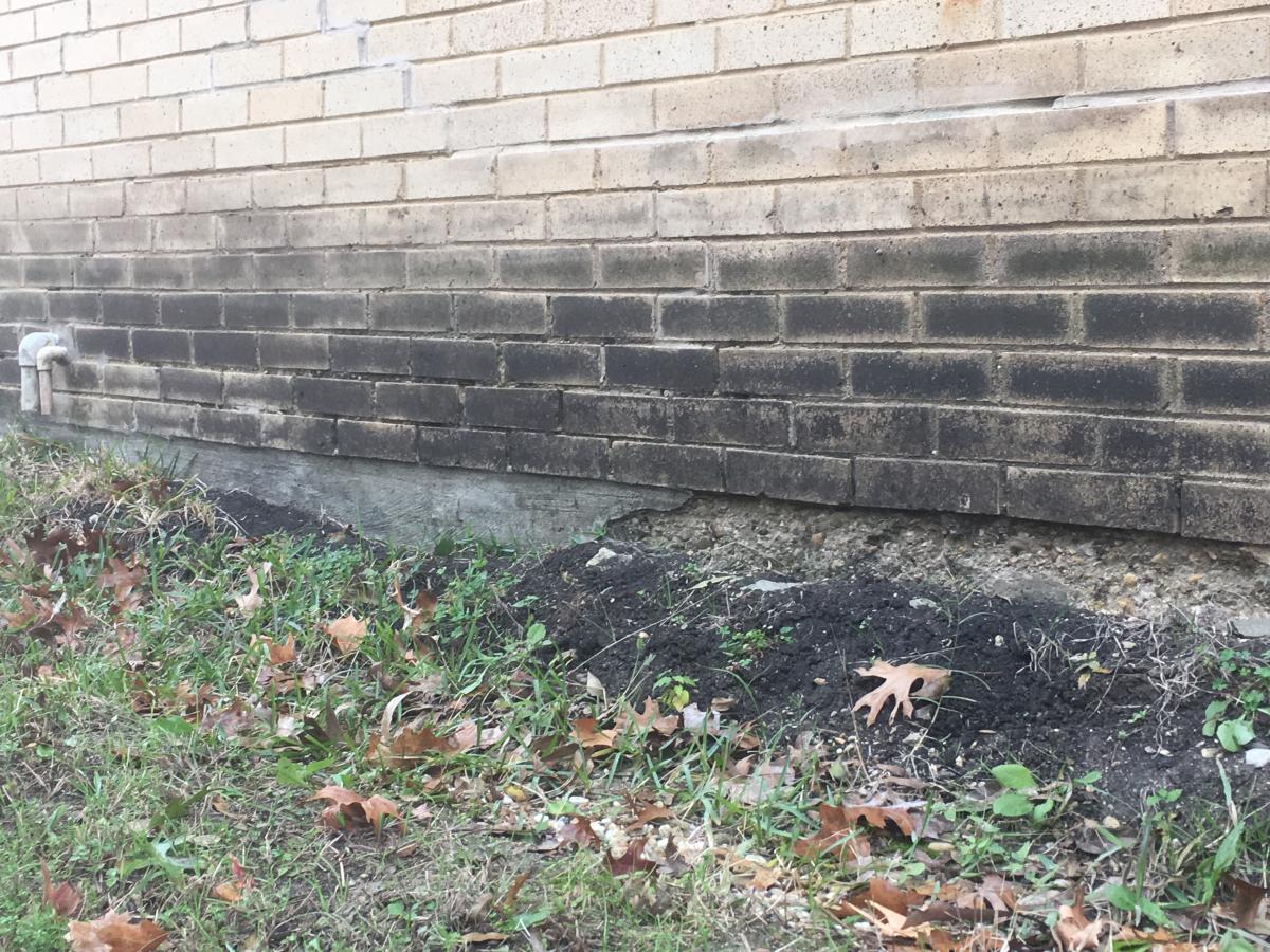
Retrofitting to add base of operations flashing involves removing a portion of the cladding at the bottom of exterior walls. This tends to be easiest with lap or panel siding cladding types that tin can be removed and re-installed by unscrewing fasteners, and most hard with brick and stucco claddings that require materials to be chipped out and replaced. Unflashed reservoir cladding systems (those that absorb water) such as brick and stucco, however, tend to exist responsible for the worst h2o damage (staining, leaks, and freeze-thaw). See Figure i.
For a successful base flashing retrofit, the extent of the removal of the existing cladding need merely be whatever is sufficient to strip-in the new metallic or rigid plastic flashing with the water control layer behind the cladding (encounter Scope). However, if upon removal of the cladding, rotten capsule is discovered, additional removal is recommended to remove and replace all rotten sheathing and mitigate the cause of the impairment. Brick claddings practice not differ from other cladding systems in that the extent of the removal tin be express to only what is required to add the new flashing; however, this may be an first-class time to consider repointing the mortar at the base of the wall. Look to the existing blueprint of staining and damage for an indication of where to repoint. When the brick is replaced, weeps should also be added to the mortar joints. See Figure vii in the Clarification Tab.
How to Add Flashing to the Base of an Existing Wall
- Remove a portion of the cladding at the base of the wall and examine the condition of the exposed building wrap, felt newspaper, or water control membrane, also every bit the sheathing below it.
- Repair torn or otherwise damaged building wrap every bit needed.
- Appraise the status of the capsule. Damp capsule will dry with improved drainage, but rotting sheathing should exist removed and replaced. If rotten sheathing is discovered, remove as much cladding as is necessary to discover and repair the source of the water entry and to remove and supplant all damaged sheathing. Install new flashing and weather condition-resistant barrier (fluid practical membrane, building newspaper, or felt) as needed.
- Afterward the cladding has been temporarily removed at the base of the wall and if the sheathing is sound (or after damaged sheathing has been repaired), follow the guidance in the Scope and Description tabs to install new base of operations flashing.
- If at that place is no carve up water control membrane on the sheathing backside the cladding, record or seal the elevation edge of the new flashing straight to the face of the existing sheathing with cocky-adhered membrane, sheathing record, or sealant. Follow the substrate preparation instructions of the membrane, tape, or sealant manufacturer to ensure proper long-term adhesion.
COMPLIANCE
See Compliance tab.
Access to some references may require buy from the publisher. While we continually update our database, links may have changed since posting. Delight contact our webmaster if you detect cleaved links.
References and Resources*
*For non-dated media, such as websites, the date listed is the engagement accessed.
Contributors to this Guide
The following authors and organizations contributed to the content in this Guide.
Mobile Field Kit
The Building America Field Kit allows you to salve items to your profile for review or employ on-site.
Sign Up or Log In
Did you observe this data helpful?
Source: https://basc.pnnl.gov/resource-guides/flashing-bottom-exterior-walls
0 Response to "what type of cover to install at ground level for a curb stop"
Post a Comment